USA/Internship
USA/Vehicle
USA/RentACar
USA/EastCoast
USA/Tourism
Electronic/Geiger
Dev/Wireshark
Mecanique/ZX6R 1998/Carburation
Mecanique/ZX6R 1998/Distribution
Latex
Linux/Super-dd
Linux/Bash
Musique/Tablatures
AsmX86
Basic

Geiger counter with LCD
Introduction
This page presents a curious way to build a Geiger counter: build it out of obsolete parts. The project is based on a PIC16F84 processor (which I have in large quantities), an overly available Russian Geiger tube (СБМ20, $20 maximum inc. deliv. on eBay), and an overly available LCD display pack (Hitachi HD44780).
I'd like to thank John Giametti (https://sites.google.com/site/diygeigercounter/), who has personally helped me solve the impulse signal noise issue, and suggested me to use the interrupt logic on the PIC. I've also used his high-voltage generation circuit :).
The following web pages (and their authors) helped me address some implementation issues:
- http://homepage.cs.uiowa.edu/~jones/bcd/decimal.html, helped me do the computation of huge numbers on an 8-bit machine.
- http://joshuagalloway.com/lcd.html, helped me use the LCD.
Theory
The Geiger tube acts as a particle detector. It needs some high-voltage. We're gonna generate that high-voltage using some analog circuit, then process its output through some interrupt on the processor. Every Xth of a second, the processor will enter into the display mode, thus compute and display the results.
The counting theory and the 8-bit computations (additions and divisions) have been previously tested using Java. See the download section for the source code.
The hardware
Schematics
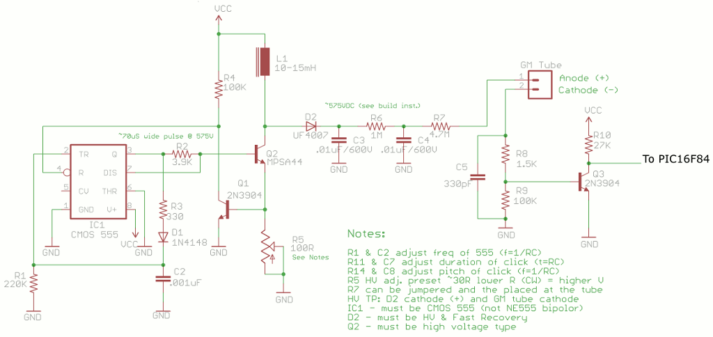
I've *ripped off* some schematic from John Giametti (with his permission), showing only the parts used. The original work can be downloaded from his website. Don't pay attention to those electronic parts that are listed, but not present on the schematic. The ones that are present however, can help adjust the circuit.
Non-standard parts
- PIC16F84, 4Mhz
- A precise 4Mhz quartz
- Russian Geiger tube СБМ20 (= SBM20)
- 20mH inductance, 0.5A
- LCD controller, Hitachi HD44780 like
About the PIC16F84
The PIC16F84 is a simple fixed-cycle, 8-bit processor. It is cheap and can be easily programmed using widely available tools. It can contain up to 1024 instructions, which is sufficient for us (but we're close to the limit).
About the СБМ20
The СБМ20 is an old Russian Geiger tube. It needs 400V to work properly, and can detect Gamma radiations (and also some Beta). It has a dead time of 190µs: during that time, no radiation can be seen by the tube. If you do simple maths, you can suppose that it can *theoretically* handle up to 5263 counts per second. That's 315780 CPM (Counts Per Minute).
The Radex RD1503 uses the same type of Geiger tube. Thus I used the same conversion from ticks to µSv/h: X counts per 40 second range -> (X/100) µSv/h. In terms of Standard Units, that's a full range of 0.00µSv/h to 2105.20µSv/h. Sufficient enough to cover the radioactivity emission range from background radiation to high radiation areas in nuclear plants (see Wikipedia's page on Sievert for details).
A little warning
Please pay attention when manipulating the high-voltage parts!
The software
How to use
As soon as the PIC is powered on, it displays a nice signature on the LCD (very short), then begins counting. Every 10 seconds, it will display the radioactivity levels in µSv/h (line 1) and CPM (line 2). Every second, if sufficient ticks are received for the computation to be some way *accurate*, the LCD will display an approximation of the radiation level, in µSv/h only (also on line 1). It will not display the CPM (on line 2), but only '~' characters, so that you can tell when it's displaying approximate values or more statistically accurate ones.
Ticks processing
Ticks are processed through the use of hardware INTerruptions. The interrupt section takes approx. 20 cycles to switch, compute and return to the original position. There's some mechanism implemented to take into account that delay in the compute and display procedures, so that the results are always of an acceptable accuracy, regardless of the number of ticks that have been processed.
Software validation
8-bit processors don't support values superior to 255 (oh wait, what?!). Moreover, old PICs like the PIC16F84 don't have divisions. We must therefore do some fine maths, in order to achieve this kind of processing. Hopefully, the software has been validated with the help of Java.
Divisions
Here is the list of the functions implemented:
- 3
- 5
- 7
- 10
- 11
The version 1.1 does not make use of all these divisions, but rather makes use of approximations.
Decimal conversion
The decode20(approx) function: takes in a value between 0 and 999999, and gives out a 6-digit, decimal value. This function is used to display the values on the LCD screen.
The source code to the PIC and the validation code
Some pics
It works!
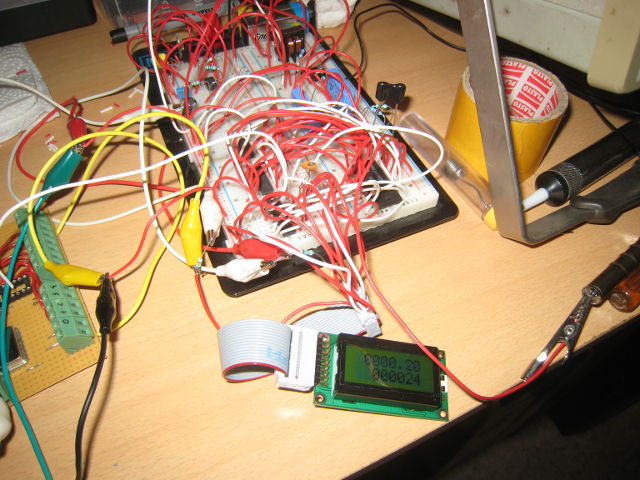
Radioactivity levels: normal.
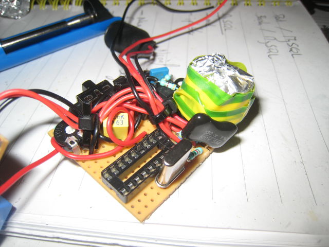
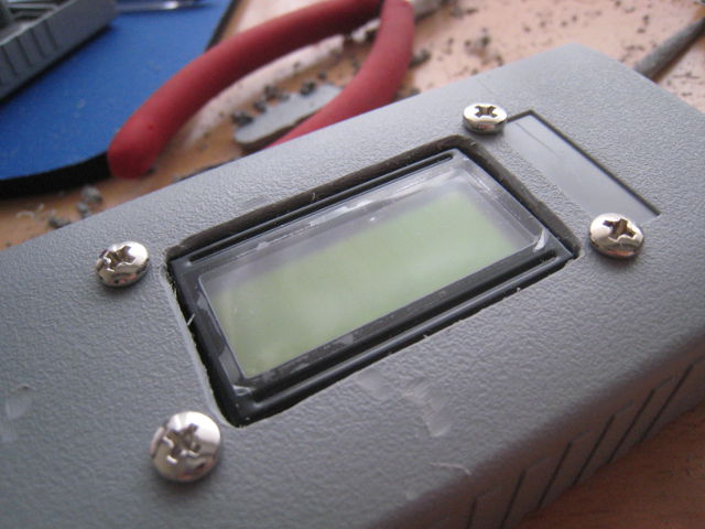
Assembling things

Issues

I still have some interferences in the signal from the Geiger tube, due to the proximity of the inductor / its type. STILL IN PROGRESS.